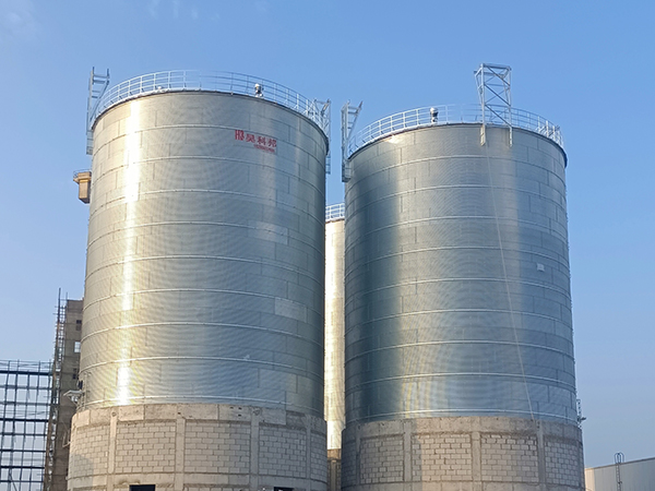
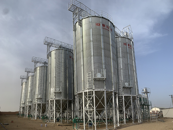
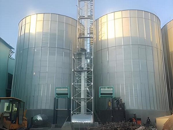
Wind and earthquakes are two forces you cannot ignore when designing grain silos. Get the design wrong, and you don’t just lose a structure—you lose grain. You lose months of inventory. You risk injury. You face downtime right when you need storage most. For grain terminals, feed mills, and on-farm storage, proper wind and seismic design isn’t just about meeting codes—it’s about keeping your operation running when nature hits.
COBAN manufactures a full range of grain storage solutions: bolted steel silos, welded silos, hopper bottom silos, and flat bottom silos. Each type handles wind and seismic loads differently based on height, diameter, and wall thickness.
This article walks through what actually affects structural performance under wind and seismic loads, where typical designs fail, and how to engineer for safety—with real numbers and code references you can use.
Why Wind and Seismic Design Matters in Grain Storage
In most grain handling regions, wind and seismic loads are the two biggest external forces acting on silos. Wind controls in flat, open areas like the U.S. Midwest or Australia. Seismic controls in active zones like Japan, Turkey, Chile, or China’s Sichuan province. If you’re in a moderate zone, both matter equally.
When design is inadequate, you see the same failures over and over:
Silo walls buckling under wind pressure
Roof panels peeling off during storms
Bolted joints failing in an earthquake
Foundation anchors pulling out of concrete
Grain shifting sideways, collapsing the wall
Total silo knockdown in high winds or strong shaking
Improve wind and seismic design, and you protect your inventory. Simple as that.
Where Typical Designs Fail
Before you specify a silo, you need to know where standard designs fall short.
| Problem Area | Typical Consequence |
|---|---|
| Thin wall sections | Buckling under wind suction |
| Insufficient stiffeners | Wall deformation during shaking |
| Poor roof-to-wall connection | Roof blow-off or collapse |
| Missing tie-down anchors | Overturning in uplift |
| Ignoring grain pressure dynamics | Wall burst during seismic horizontal load |
| Under-designed discharge hopper | Hopper separation during shaking |
Each one of these can be fixed with better engineering, thicker steel, and the right silo type for your site.

1. Know Your Site – Wind Speed and Seismic Zone Come First
You can’t design for what you don’t measure. Wind and seismic design starts with site data.
Wind Design Parameters
Most codes (ASCE 7, Eurocode 1, GB 50009) require these inputs:
| Parameter | Typical Value Range | What Affects It |
|---|---|---|
| Basic wind speed (3-second gust) | 90–150 mph (40–67 m/s) | Local weather data |
| Exposure category | B (urban) to D (flat open) | Surrounding terrain |
| Importance factor | 1.0 (standard) to 1.15 (high-risk) | Consequence of failure |
| Topographic factor | 1.0–1.4 | Hills, ridges, escarpments |
For most grain silos, design wind speed starts at 115 mph (51 m/s) in standard zones. In cyclone-prone areas like North Queensland or the Gulf Coast, design speeds hit 150 mph (67 m/s) or higher.
Seismic Design Parameters
Seismic design requires zone-specific data:
| Parameter | Typical Value Range | Code Reference |
|---|---|---|
| Spectral acceleration (S_s, S_1) | 0.1g–1.5g | Site hazard map |
| Site class | A (hard rock) to E (soft soil) | Geotech report |
| Seismic design category (SDC) | A (low) to F (high) | Combined S_s and S_1 |
| Response modification factor (R) | 1.5–3.0 for silos | ASCE 7 Chapter 15 |
A silo on soft soil (Site Class E) can see ground motion amplified by 2–3x compared to rock. Same earthquake. Different damage.
What the data says: The 2011 Christchurch earthquake (NZ) damaged over 80% of steel silos on soft soil. Silos on stiff soil or rock had less than 15% damage. Site class matters as much as the silo design.
2. Understand the Loads – Wind and Seismic Work Differently
Wind and seismic loads act differently on silos. One is pressure on the outside. The other is inertia from the inside.
Wind Loads on Silos
Wind creates three effects on a cylindrical silo:
| Load Type | Where It Acts | Failure Mode |
|---|---|---|
| External pressure (windward) | Compression on front face | Wall buckling |
| External suction (leeward/sides) | Tension on sides and back | Panel pull-out |
| Uplift (roof) | Vertical lift on roof | Roof blow-off |
| Overturning moment | Entire structure | Anchor pull-out |
Wind pressure follows this formula: q = 0.5 × ρ × V² × C
At 120 mph (53.6 m/s), wind pressure hits about 36 psf (1.72 kPa) on a flat surface. On a silo, the shape factor (C) varies from +0.8 on the windward side to -1.2 on the sides and leeward. That suction side is usually the worst—it pulls panels outward.
Seismic Loads on Silos
Seismic loads are different. The silo itself has mass. The grain inside has even more mass. When the ground shakes, both masses want to stay still. That creates horizontal forces.
| Load Type | Source | Failure Mode |
|---|---|---|
| Wall inertial force | Silo steel mass | Wall buckling mid-height |
| Grain dynamic pressure | Grain mass moving laterally | Hoop tension failure, wall burst |
| Vertical acceleration | Up-down shaking | Anchor tension, column buckling |
| Overturning | Differential wall/grain motion | Silo tipping or sliding |
Seismic base shear is calculated as: V = C_s × W
Where C_s (seismic coefficient) typically ranges from 0.1g to 0.5g depending on zone and soil. Multiply by the total weight (empty silo + full grain), and you get the horizontal force at the base.
For a 10,000-bushel (about 270-ton) grain silo, a C_s of 0.3g creates an 81-ton horizontal force at ground level. That’s the equivalent of an 18-wheeler hitting the silo sideways at full speed.
3. Pick the Right Silo Type for Your Load Condition
Not all silos handle wind and seismic loads the same way. The geometry changes the stress distribution.
| Silo Type | Wind Performance | Seismic Performance | Best Application |
|---|---|---|---|
| Flat bottom (tall, narrow) | High wind moment | Moderate – grain sloshing risk | Large terminals, low seismic zones |
| Hopper bottom (short, wide) | Lower wind moment | Better – grain contained | Feed mills, moderate seismic zones |
| Bolted steel (field assembled) | Good with stiffeners | Joint-dependent – bolt slip risk | All zones with proper detailing |
| Welded steel (shop fabricated) | Excellent – uniform wall | Excellent – no joint slip | High wind or high seismic zones |
| Reinforced concrete | Very good – high mass | Good – heavy, but ductile | Very large capacities (>5,000 tons) |
For high wind zones (V > 130 mph): Choose lower height-to-diameter ratios (H/D < 2.0). Shorter, wider silos have lower wind overturning moments. A silo with H/D = 1.5 sees about 60% less overturning moment than H/D = 3.0 for the same diameter.
For high seismic zones (S_s > 0.5g): Choose hopper bottom or flat bottom with internal bracing. Avoid tall, slender silos. Grain sloshing in a tall flat-bottom silo during an earthquake creates dynamic pressures 2–3x higher than static grain pressures.
COBAN’s bolted steel silos use double-lap bolted seams with Grade 8.8 or 10.9 bolts for seismic zones. In welded configurations, continuous seams eliminate joint slip entirely—preferred for SDC D, E, or F zones.
4. Design the Wall – Buckling Is the Hidden Failure
Wall buckling under wind suction is the most common wind failure I see. The wind pulls outward, the wall is in tension, but thin panels buckle inward like a crushed soda can.
Wind Buckling Criteria
The critical wind pressure for buckling is:
P_cr = 0.5 × E × (t/D) × (t/L)
Where:
E = steel modulus (29,000 ksi or 200 GPa)
t = wall thickness
D = silo diameter
L = vertical spacing between stiffeners
Real numbers
| Silo Diameter (m) | Wall Thickness (mm) | Stiffener Spacing (m) | Buckling Pressure (kPa) | Max Wind Speed (m/s) |
|---|---|---|---|---|
| 5 | 3 | 1.5 | 2.1 | 58 (130 mph) |
| 5 | 4 | 1.5 | 3.7 | 77 (172 mph) |
| 8 | 4 | 1.5 | 1.5 | 49 (110 mph) |
| 8 | 5 | 1.0 | 3.6 | 76 (170 mph) |
Notice: Increasing diameter from 5m to 8m drops buckling pressure by 60% unless you increase thickness or tighten stiffener spacing.
What to do: For silos over 6m diameter in wind zones > 120 mph, specify wall thickness ≥ 5mm and stiffener spacing ≤ 1.2m. Or use helical stiffeners (spiral ribs) which increase buckling resistance by 40–60% compared to vertical stiffeners alone.
Seismic Wall Demands
For seismic, the wall faces hoop tension from grain pressure. During an earthquake, grain pressure on the wall increases by a factor called C_h (horizontal seismic coefficient).
Dynamic hoop tension = static hoop tension × (1 + 2 × C_h)
For C_h = 0.3, dynamic hoop tension = static × 1.6. That means a wall designed for static pressure only is suddenly 60% overloaded when the ground shakes.
What to do: In seismic zones, design walls for 1.5–2.0x static grain pressure. That typically adds 1–2mm to wall thickness or requires closer bolt spacing on bolted silos.
5. Anchor It Down – Overturning and Uplift Are Real
Silos are light when empty and heavy when full. Wind and seismic both create overturning moments. The anchor system has to resist these forces.
Wind Overturning
For an empty silo, wind uplift at the base can exceed the silo’s self-weight. That’s when anchors pull out or the silo lifts off the foundation.
Example calculation:
Silo diameter: 6m
Silo height: 12m (H/D = 2.0)
Empty weight: 12 tons
Wind speed: 130 mph (58 m/s)
Wind uplift force: ~8 tons
The wind uplift (8 tons) is less than the empty weight (12 tons), so the silo won’t lift. But wind overturning moment tries to tip it. The windward anchor sees tension. The leeward anchor sees compression.
For this example, the maximum anchor tension is about 4.5 tons per anchor. A standard 20mm anchor bolt in good concrete can handle 6–8 tons. So it’s safe—barely.
At 150 mph (67 m/s), wind uplift jumps to ~12 tons. Now uplift > empty weight. The silo wants to lift off the foundation entirely. That’s when you need tie-downs, heavier base plates, or a taller foundation.
Seismic Overturning
For seismic, a full silo is worse. The grain mass adds to the overturning moment.
Example calculation (same silo, full of corn at 45 tons total weight):
Seismic coefficient C_s = 0.3g
Base shear V = 0.3 × 45 = 13.5 tons
Overturning moment = 13.5 tons × 6m (center of mass height) = 81 ton-m
Anchor tension at windward side = ~7 tons per anchor
That’s near the limit of a 20mm anchor bolt. For C_s = 0.4g, anchor tension hits 9–10 tons—well beyond standard anchors.
What to do: For seismic zones with S_s > 0.4g, use larger anchor bolts (25–30mm diameter), deeper embedment (≥ 300mm into concrete), or a continuous ring foundation with anchor spacing ≤ 1.5m.
6. Connect the Roof – Don’t Let It Blow Off
The roof is the most neglected part of wind design. It’s also the first thing to fail in a storm.
Roof panels experience suction as wind flows over the top. The suction pressure can be 1.5–2.0x higher than side wall pressure.
Typical roof failures:
Panel screws pull through the sheet
Panel seams separate
Roof structure separates from the silo wall ring
Entire roof lifts off and flies away
What the data says: In a 2019 post-storm survey of 47 damaged grain silos in Nebraska (wind speeds 100–120 mph), 33 had roof damage. Only 14 had wall damage. Roofs fail first.
What to do:
| Roof Design Feature | Standard | High Wind (>120 mph) |
|---|---|---|
| Panel thickness | 0.5–0.7mm | 0.7–1.0mm |
| Screw spacing (edge) | 200mm | 150mm |
| Screw spacing (field) | 300mm | 200mm |
| Roof-to-wall connection | Intermittent weld | Continuous angle ring |
| Roof pitch | 15–20° | 25–30° (reduces suction) |
For seismic zones, roof connections also matter. A welded ring at the roof-to-wall junction prevents the roof from separating during shaking. COBAN’s silos for SDC D and above use a continuous top ring with full penetration welds—no intermittent stitching.
7. Don’t Forget the Discharge Hopper – It Takes Seismic Loads Differently
The discharge hopper at the bottom of a silo sees unique seismic loads. The grain inside the hopper pushes outward and downward simultaneously. During shaking, that pressure cycles rapidly.
Hopper failures in earthquakes:
Hopper cone buckling (compression rings fail)
Hopper-to-skirt weld cracking
Hopper support leg buckling
Flow obstruction from internal bracing
What to do:
Design hopper cone thickness at least 1.5x wall thickness above the transition
Use external stiffener rings on hopper (not internal—internal rings trap grain)
For bolted hoppers, specify Grade 10.9 bolts with double nuts
For welded hoppers, use full penetration welds at all seams
COBAN’s hopper bottom silos use reinforced cone sections with external ring stiffeners at 500–800mm spacing for seismic zones. The transition joint (cylindrical wall to hopper cone) gets a heavy ring beam—typically a 150×150×10mm angle or a fabricated box section.
What Good Wind and Seismic Design Looks Like – Technical Benchmarks
Here are typical design parameters for grain silos in different risk zones. These assume standard geometry (H/D = 1.5–2.0, diameter 5–10m).
| Parameter | Low Risk (V < 100 mph, S_s < 0.2g) | Moderate Risk (V = 100–120 mph, S_s = 0.2–0.4g) | High Risk (V > 120 mph, S_s > 0.4g) |
|---|---|---|---|
| Wall thickness (mm) | 3–4 | 4–5 | 5–7 |
| Stiffener spacing (m) | 1.5–2.0 | 1.2–1.5 | 0.8–1.2 |
| Anchor bolt diameter (mm) | 16–20 | 20–24 | 24–30 |
| Anchor spacing (m) | 2.0–2.5 | 1.5–2.0 | 1.0–1.5 |
| Roof panel thickness (mm) | 0.5 | 0.6–0.7 | 0.8–1.0 |
| Roof screw spacing (mm) | 200–300 | 150–200 | 150 (all edges) |
| Roof-to-wall connection | Bolted or stitch weld | Continuous angle | Continuous ring + welds |
| Transition ring beam | Optional | Standard | Heavy (100×100×8mm min) |
| Design factor of safety | 1.5 | 2.0 | 2.5 |
Your actual numbers will vary by exact site conditions, but these are good targets for new construction or retrofits.
Where Better Design Pays Off
Grain storage facilities see the biggest returns from proper wind and seismic design in these situations:
Coastal regions with cyclone risk: One storm can destroy 20–30% of poorly anchored silos. Good design cuts that to near zero.
Active seismic zones like Japan, Turkey, or California: A moderate earthquake (M6–7) can shut down a terminal for months if silos collapse. Proper design means you’re back online in days.
High-value grain storage: Single silos holding $200,000+ of grain. Collapse isn’t just structural loss—it’s inventory loss.
Multi-silo terminals with 10,000+ tons capacity: Cascading failure—one silo falls into the next. Proper anchoring and spacing prevent domino effects.
Insurance and compliance: Many insurers require third-party wind/seismic certification for silos over 500 tons. Good design lowers premiums.
Pick the right silo type. Design for your actual site loads. Specify thicker walls and stronger connections than the minimum code requires. And you’ll avoid the failures that take down other facilities.
Conclusion
Proper wind and seismic design for grain silos comes down to a few things. Know your site wind speed and seismic zone. Understand how loads differ—wind pulls outward and overturns, seismic shakes horizontally and creates dynamic grain pressure. Pick the right silo type for your risk level. Design walls for buckling, not just static pressure. Anchor the silo so it can’t lift or tip. Connect the roof so it doesn’t blow off. And don’t forget the hopper—it takes loads differently than the cylindrical wall.
COBAN builds bolted steel silos, welded silos, hopper bottom silos, and flat bottom silos. Each type can be engineered for specific wind and seismic conditions—thicker walls, tighter stiffener spacing, stronger anchors, reinforced roofs, and heavy transition rings. Match the design to the site hazard, follow the guidelines above, and you’ll get silos that stay standing when the wind howls or the ground shakes.
With climate patterns changing and seismic codes getting stricter, proper wind and seismic design isn’t optional anymore. It’s how you protect your grain and keep your operation running.